
A modular connector is a type of electrical connector for cords and cables of electronic devices and appliances, such in computer networking, telecommunication equipment, and audio headsets.
Modular connectors were originally developed for use on specific Bell System telephone sets in the 1960s, and similar types found use for simple interconnection of customer-provided telephone subscriber premises equipment to the telephone network. The Federal Communications Commission (FCC) mandated in 1976 an interface registration system, in which they became known as registered jacks. The convenience of prior existence for designers and ease of use led to a proliferation of modular connectors for many other applications. Many applications that originally used a bulkier, more expensive connector have converted to modular connectors. Probably the best known applications of modular connectors are for telephone and Ethernet.
Accordingly, various electronic interface specifications exist for applications using modular connectors, which prescribe physical characteristics and assign electrical signals to their contacts.
Nomenclature
Modular connectors are often referred to as modular phone jack and plug, RJ connector, and Western jack and plug. The term modular connector arose from its original use in modular wiring components of telephone equipment by the Western Electric Company in the 1960s. This includes the 6P2C used for telephone line connections and 4P4C used for handset connectors.
Registered jack designations describe the signals and wiring used for voice and data communication at customer-facing interfaces of the public switched telephone network. It is common to use a registered jack number to refer to the physical connector itself; for instance, the 8P8C modular connector type is often inaccurately labeled RJ45 because the registered jack standard of that name specified 8P8C modular connectors. A common use of 8P8C connectors is Ethernet over twisted pair. Likewise, the 4P4C connector is sometimes erroneously called RJ9 or RJ22—no such official designations exist—and various six-position modular connectors may be incorrectly called RJ11.
History
The first types of small modular telephone connectors were created by AT&T in the mid-1960s for the plug-in handset and line cords of the Trimline telephone. Driven by demand for multiple sets in residences with various lengths of cords, the Bell System introduced customer-connectable part kits and telephones, sold through PhoneCenter stores in the early 1970s. For this purpose, Illinois Bell started installing modular telephone sets on a limited scale in June 1972. The patents by Edwin C. Hardesty and coworkers, US 3699498 (1972) and US 3860316 (1975), followed by other improvements, were the basis for the modular molded-plastic connectors that became commonplace for telephone cords by the 1980s. In 1976, these connectors were standardized nationally in the United States by the Registration Interface program of the Federal Communications Commission (FCC), which designated a series of Registered Jack (RJ) specifications for interconnection of customer-premises equipment to the public switched telephone network (PSTN).
Gender
Modular connectors have gender: plugs are considered to be male, while jacks or sockets are considered to be female. Plugs are used to terminate cables and cords, while jacks are used for fixed locations on surfaces of walls, panels, and equipment. Other than telephone extension cables, cables with a modular plug on one end and a jack on the other are rare. Instead, cables are usually connected using a female-to-female coupler, having two jacks wired back-to-back.
Latching tab and orientation
Modular connectors are designed to latch together. As a plug is inserted into a jack, a plastic tab on the plug locks so that the plug cannot be pulled out. To remove the plug, the latching tab must be depressed against the plug to clear the locking edge. The standard orientation for installing a jack in a wall or panel is with the tab down.
The latching tab may easily snag on other cables and break off resulting in loss of the secure latching feature. To prevent this, tabs are often protected with a boot over the plug, or a special tab design, on snagless cords. Most protective boots must be installed onto a cable before the modular plug is crimped on. This means that field retrofitting of these types of boots is not possible. However, protective boots or rigid protective ramp adapters are available which can be snapped over an installed unprotected modular plug.
Size and contacts
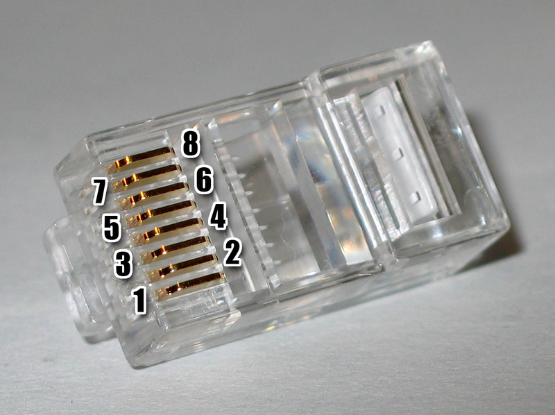
8P8C modular plug pin numbering.
Modular connectors are designated using two numbers that represent the maximum number of contact positions and the number of installed contacts, with each number followed by P and C, respectively. For example, 6P2C is a connector having six positions and two installed contacts. Alternate designations omit the letters while separating the position and contact quantities with either an x (6x2) or a slash (6/2).
When not installed, contacts are usually omitted from the outer positions inward, such that the number of contacts is almost always even. The connector body positions with omitted or unconnected contacts are unused for the electrical connection but ensure that the plug fits correctly. For instance, RJ11 cables often have connectors with six positions and four contacts, to which are attached just two wires.
The contact positions are numbered sequentially starting from 1. When viewed head-on with the retention mechanism on the bottom, jacks will have contact position number 1 on the left and plugs will have it on the right. Contacts are numbered by the contact position. For example, on a six-position, two-contact plug, where the outermost four positions do not have contacts, the innermost two contacts are numbered 3 and 4.
Modular connectors are manufactured in four sizes, with 4-, 6-, 8-, and 10-positions. The insulating plastic bodies of 4P and 6P connectors have different widths, whereas 8P or 10P connectors share an even larger body width.
Insulation displacement contact types
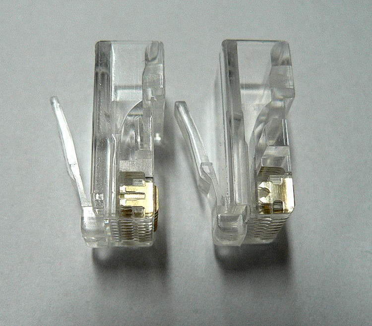
8P8C plug with contacts for solid wire (left) and stranded wire (right)
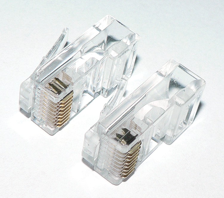
Contacts for solid wire (top left) and stranded wire (bottom right)
Internally, the contacts on the plugs have sharp prongs that, when crimped, pierce the wire insulation and connect with the conductor, a mechanism known as insulation displacement. Ethernet cables, in particular, may have solid or stranded (tinsel wire) conductors and the sharp prongs are different in the 8P8C connectors made for each type of wire. A modular plug for solid (single-strand) wire often has three slightly splayed prongs on each contact to securely surround and grip the conductor. Modular plugs for stranded have prongs that are designed to connect to multiple wire strands. Connector plugs are designed for either solid or stranded wire and a mismatch between plug and wire type may result in an unreliable connection.
Interchangeability
Some modular connectors are indexed, meaning their dimensions are intentionally non-standard, preventing connections with connectors of standard dimensions. The means of indexing may be non-standard cross-sectional dimensions or shapes, retention mechanism dimensions or configuration. For example, a Modified Modular Jack using an offset latching tab was developed by Digital Equipment Corporation to prevent accidental interchange of data and telephone cables.
The dimensions of modular connectors are such that a narrower plug can be inserted into a wider jack that has more positions than the plug, leaving the jack's outermost contacts unconnected. The contact spacing is always 1.02 mm (center to center). However, not all plugs from all manufacturers have this capability, and some jack manufacturers warn that their jacks are not designed to accept smaller plugs without damage. If an inserted plug lacks slots to accommodate the jack's contacts at the outermost extremes, it may permanently deform those outermost contacts of an incompatible jack. Excessive resistance may be encountered when inserting an incompatible plug, as the outermost contacts in the jack are forcibly deformed.
Special modular plugs have been manufactured (for example, the Siemon UP-2468) which have extra slots beyond their standard contacts, to accommodate the wider jack's outermost contacts without damage. These special plug connectors can be visually identified by carefully looking for the extra slots molded into the plug. The molded plastic bodies of the special plugs may also be colored with a light blueish tinge, to aid in quick recognition. The special plugs are preferred for test equipment and adapters, which may be rapidly connected to a large number of corresponding connectors in quick succession for testing purposes. The use of the special plugs avoids inadvertent damage to the equipment under test, even when a narrower plug is inserted into a nominally incompatible wider jack.
Termination
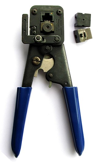
A modular plug crimping tool with exchangeable crimping dies.
Termination of cables with modular connectors is similar across the various number of positions and contacts in the plug. The crimping tool contains a die which is often exchangeable and is closely matched to the shape and pin count of the modular plug.
A crimping die-set looks similar to an 8P8C jack, except for the eight teeth lining the top portion of the die. When the tool is operated, the die compresses around the 8P8C plug. As the die compresses, these teeth force the plug contacts into the conductors of the cable being terminated. The crimper may also permanently deform part of the plastic plug body in such a way that it grips the outer sheath of the cable for secure fastening and strain relief. These actions permanently attach the plug to the cable.
Pinout
The contact assignments (pinout) of modular connectors vary by application. Telephone network connections are standardized by registered jack designations, and Ethernet over twisted pair is specified by the TIA/EIA-568 standard. For other applications, standardization may be lacking; for example, multiple conventions exist for the use of 8P8C connectors in RS-232 applications. For this reason, D-sub-to-modular adapters are typically shipped with the D-sub contacts (pins or sockets) terminated but not inserted into the connector body, so that the D-sub-to-modular contact pairing can be assigned as needed.
4P4C
4P4C modular connector on a handset cord.
Wired telephone that uses 4P4C connectors for the coiled handset cord.
The four-position four-conductor (4P4C) connector is the standard modular connector used on both ends of telephone handset cords, and is therefore often called a handset connector.
This handset connector is not a registered jack, because it was not intended to connect directly to telephone lines. However it is often referred to as RJ9, RJ10, or RJ22.
Handset wiring

Wiring diagram of 4P4C/RJ9 connector in telephone handset cord.
Handsets and often headsets for use with telephones commonly use a 4P4C connector. The two center pins are commonly used for the receiver, and the outer pins connect the transmitter so that a reversal of conductors between the ends of a cord does not affect the signal routing. This may differ for other equipment, including hands-free headsets.
Data port
The Macintosh 128K, Macintosh 512K and Macintosh Plus from Apple as well as the Amiga 1000 from Commodore used 4P4C connectors to connect the keyboard to the main computer housing. The connector provided power to the keyboard on the outer two contacts and received data signals on the inner pair. The cable between the computer and the keyboard was a coiled cord with an appearance very similar to a telephone handset cable. The connector on the Amiga 1000 used crossover wiring, similar to a telephone handset. The connector wiring on the Apple computers, however, required a polarized straight through pinout. Using a telephone handset cable instead of the supplied cable could short out the +5 volt DC supply and damage the Apple computer or the keyboard.
Modular connectors are often used for data links, such as serial line connections, because of their compact dimensions. For example, some DirecTV set top boxes include a 4P4C data port connector with an adapter cord to a computer serial port so that remote control is possible from the computer.
6P6C
6P4C crimp-on style connector.
Modular plugs are described by the maximum number of physical contact positions and the actual number of contacts installed in these positions. The 6P2C, 6P4C, and 6P6C modular connectors are probably best known for their use as RJ11, RJ14, and RJ25 registered jacks, respectively. These interfaces use the same six-position modular connector body, but have different numbers of pins installed.
RJ11 is a physical interface often used for terminating single telephone lines. RJ14 is similar, but for two lines, and RJ25 is for three lines. RJ61 is a similar registered jack for four lines, but uses an 8P8C connector.
RJ11 wiring
6P6C connector showing the location of pin 1.
Cables sold as RJ11 often actually use 6P4C connectors (six positions, four contacts) and RJ14 wiring – four wires running to a central junction box. Two of its six possible contact positions connect tip and ring, and the other two contact positions may be unused or provide low-voltage power for night-light or other features on the telephone set. In some installations an extra contact was also required for the ground connection for selective ringers.
Pinout
The pins of the 6P6C connector are numbered 1 to 6, counting left to right when holding the connector tab side down with the opening for the cable facing the viewer.
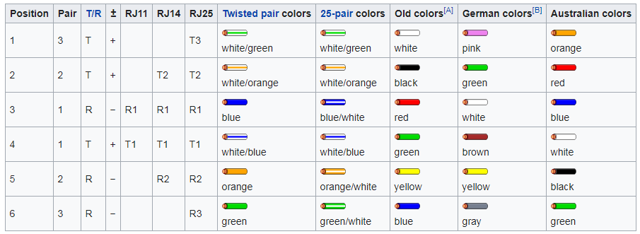
- While the old solid color code was well established for pair 1 and usually pair 2, there are several conflicting conventions for pair 3 (and sometimes even pair 2). The colors shown above were taken from a vendor of "silver satin" flat 8-conductor phone cable that claims to be standard. 6-pair solid (old) bellwire cables previously used by the Bell System use white for pair 3 tip but some vendors' cable may substitute orange for white. At least one other vendor of flat 8-conductor cable uses the sequence blue, orange, black, red, green, yellow, brown and white/slate.
- This color scheme originates in the (withdrawn) national standard DIN 47100. The scheme shown here is the correct color code for interfacing with the RJ connector standards.
However, with German domestic telephone equipment, and that in some neighboring countries, 6P4C plugs and sockets are typically only used to connect the telephone cord to the phone base unit, whereas the mechanically different TAE connector is used at the other end to connect to a service provider interface. Older base units may accommodate the additional connectors of TAE (E, W, a2, b2) and may feature non-RJ standard sockets that can be connected directly to TAE plugs. Further, flat DIN 47100 cables typically place the wires in ascending order. When used directly with 6P4C plugs, the color coding may be undetermined.
Powered version of RJ11
In the powered version of the RJ11 interface, pins 2 and 5 (black and yellow) may carry low voltage AC or DC power. While the telephone line on pins 3 and 4 (red and green) supplies enough power for most telephone terminals, old telephone terminals with incandescent lights, such as the Western Electric Princess and Trimline telephones, need more power than the phone line can supply. Typically, the power on pins 2 and 5 is supplied by an AC adapter plugged into a nearby power outlet which potentially even supplies power to all of the jacks in the house.
Compatibility with structured cabling
Structured cabling networks adhering to TIA/EIA-568-B, ISO/IEC 11801 (or ISO/IEC 15018 for home networks) are widely used for both computer networking and analog telephony. These standards specify the T568-A or T568-B pin-outs compatible with Ethernet. The 8P8C jack used by structured cabling physically accepts the 6-position connector used by RJ11, RJ14 and RJ25. Only RJ11 and RJ14 have full electrical compatibility because Ethernet-compatible pin-outs split the third pair of RJ25 across two separate cable pairs, rendering that pair unusable by an analog phone. Both the third and fourth pairs of RJ61 are similarly split. The incompatible T568-A/B layouts were necessary to preserve the electrical properties of the third and fourth pairs for Ethernet, which operates at much higher frequencies than analog telephony. Because of these incompatibilities, and because RJ25 and RJ61 were never very common, the T568-A/B conventions have largely displaced RJ25 and RJ61 for telephones with more than two lines.
8P8C
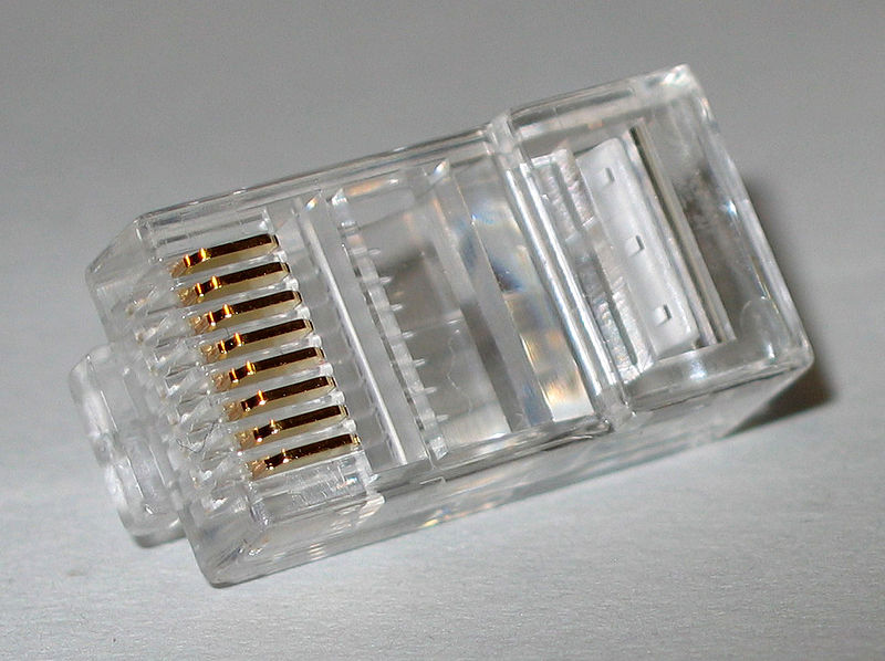
An 8P8C modular plug not yet crimped onto a cable
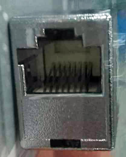
An 8P8C modular jack
The 8 position 8 contact (8P8C) connector is a modular connector commonly used to terminate twisted pair and multi-conductor flat cable. These connectors are commonly used for Ethernet over twisted pair, registered jacks and other telephone applications, RS-232 serial communication using the TIA/EIA-568 and Yost standards, and other applications involving unshielded twisted pair, shielded twisted pair, and multi-conductor flat cable.
An 8P8C modular connection consists of a male plug and a female jack, each with eight equally-spaced contacts. On the plug, the contacts are flat metal bars positioned parallel to the connector body. Inside the jack, the contacts are metal spring wires angled away from the insertion interface. When the plug is mated with the jack, the contacts meet and create an electrical connection. The spring tension of the jack contacts ensures a good interface.
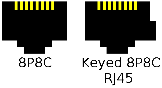
Left: Generic 8P8C (or 8PMJ, 8-position modular jack) female connector. Right: RJ45 female connector (with key)
Although commonly referred to as RJ45 in the context of Ethernet and category 5 cables, RJ-45 originally refers to a specific wiring configuration of an 8P8C connector. A telephone-system-standard RJ45 plug has a key which excludes insertion in an un-keyed 8P8C socket.
The original RJ45S[a] was intended for high-speed modems, and is obsolete. The RJ45S jack mates with a keyed 8P2C modular plug, and has pins 4 and 5 (the middle positions) wired for the ring and tip conductors of a single telephone line and pins 7 and 8 shorting a programming resistor. This is a different mechanical interface and wiring scheme than TIA/EIA-568-B with the 8P8C connector in Ethernet and telephone applications. Generic 8P8C modular connectors are similar to those used for the RJ45S variant, although the RJ45S plug is keyed and not compatible with 8P8C modular jacks.
Telephone installers who wired RJ45S modem jacks or RJ61X telephone jacks were familiar with the pin assignments of the standard. However, the standard un-keyed modular connectors became ubiquitous for computer networking and informally inherited the name RJ45.
Standardization
The shape and dimensions of an 8P8C modular connector are specified for U.S. telephone applications by the Administrative Council for Terminal Attachment (ACTA) in national standard ANSI/TIA-1096-A. This standard does not use the short term 8P8C and covers more than just 8P8C modular connectors, but the 8P8C modular connector type is the eight position connector type described therein, with eight contacts installed. The international standard is ISO-8877.
For data communication applications (LAN, structured cabling), International Standard IEC 60603 specifies in parts 7-1, 7-2, 7-4, 7-5, and 7-7 not only the same physical dimensions, but also high-frequency performance requirements for shielded and unshielded versions of this connector for frequencies up to 100, 250 and 600 MHz, respectively.
Pinout
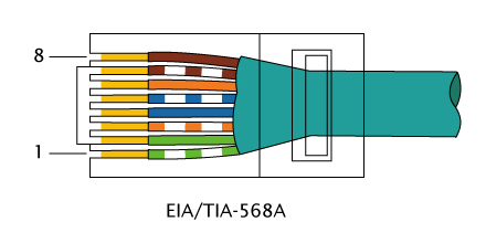
T568A wiring.
T568B wiring.
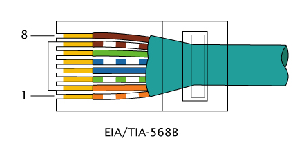
8P8C connectors are frequently terminated using the T568A or T568B assignments that are defined in TIA/EIA-568. The drawings to the right show that the copper connections and pairing are the same, the only difference is that the orange and green pairs (colors) are swapped. A cable wired as T568A at one end and wired as T568B at the other end (Tx and Rx pairs reversed) is an Ethernet crossover cable. Before the widespread acceptance of auto MDI-X capabilities, a crossover cable was needed to interconnect similar network equipment (such as Ethernet hubs to Ethernet hubs). A cable wired the same at both ends is called a "patch" or "straight-through" cable, because no pin/pair assignments are swapped. Crossover cables are sometimes still used to connect two computers together without a switch or hub, however most network interface cards (NIC) in use today implement auto MDI-X to automatically configure themselves based on the type of cable plugged into them. If a "patch" or "straight" cable is used to connect two computers with auto MDI-X capable NICs, one NIC will configure itself to swap the functions of its Tx and Rx wire pairs.
Types and compatibility
Two types of 8P8C plugs and crimping tools for installing the plug onto a cable are commonly available: Western Electric/Stewart Stamping (WE/SS) and Tyco/AMP. While both types are similar, the tooling used to install the two different plug types cannot be interchanged. WE/SS compatible plugs are available from a large number of manufacturers, whereas Tyco/AMP plugs are produced exclusively by Tyco Electronics. Both types of modular plugs can be mated with a standard 8P8C modular jack.
WE/SS and Tyco/AMP 8P8C plugs have different spacings for the cable strain relief. Using a WE/SS 8P8C crimp die set on a Tyco/AMP 8P8C plug crushes the top of the connector and damages the crimp die set, and vice versa.
Both types of 8P8C plugs are available in shielded and unshielded varieties for different attenuation tolerances as needed. Shielded plugs are more expensive and require shielded cable, but have a lower attenuation, and may reduce signal noise.
Although a narrower 4-pin and 6-pin connector fits into the wider 8-pin jack, the smaller connector can potentially damage the springs of a larger jack, because the body of the smaller connector press onto the contacts. The body of a 6P6C or 4P4C plug typically projects out by more than one millimeter further than the contacts and presses the outermost contacts of the larger connector further than if a full-size connector were inserted.
Applications
8P8C are commonly used in computer networking and telephone applications, where the plug on each end is an 8P8C modular plug wired according to a TIA/EIA standard. Most wired Ethernet network communications today are carried over Category 5e or Category 6 cable with an 8P8C modular plug crimped on each end.
The 8P8C modular connector is also used for RS-232 serial interfaces according to the EIA/TIA-561 standard. This application is common as a console interface on network equipment such as switches and routers. Other applications include other networking services such as ISDN and T1.
In floodwired[b] environments the center (blue) pair is often used to carry telephony signals. Where so wired, the physical layout of the 8P8C modular jack allows for the insertion of an RJ11 plug in the center of the jack, provided the RJ11 plug is wired in true compliance with the U.S. telephony standards (RJ11) using the center pair. The formal approach to connect telephony equipment is the insertion of a type-approved converter.
The remaining (brown) pair is increasingly used for Power over Ethernet (PoE). Legacy equipment may use just this pair; this conflicts with other equipment, because some manufacturers previously short circuited unused pairs to reduce signal crosstalk. Some routers, bridges and switches can be powered by the unused 4 lines—blues (+) and browns (−)—to carry current to the unit. There is now a standardized wiring scheme for Power over Ethernet.
Different manufacturers of 8P8C modular jacks arrange for the pins of the 8P8C modular connector jack to be linked to wire connectors (often IDC type terminals) that are in a different physical arrangement from that of other manufacturers: Thus, for example, if a technician is in the habit of connecting the white/orange wire to the "bottom right hand" IDC terminal, which links it to 8P8C modular connector pin 1, in jacks made by other manufacturers this terminal may instead connect to 8P8C modular connector pin 2 (or any other pin). Labels and manufacturer's documentation should be consulted whenever an unfamiliar connector is first encountered.
8P8C modular connectors are also commonly used as a microphone connector for PMR, LMR, and amateur radio transceivers. Frequently the pinout is different, usually mirrored (i.e. what would be pins 1 to 8 in the TIA/EIA-568 standard might be pins 8 to 1 in the radio and its manual).
In landline telephony, an 8P8C jack is used at the point a line enters the building to allow the line to be broken to insert automatic dialing equipment, including intrusion alarm panels. In analog mobile telephony, the 8P8C connector was used to connect an AMPS cellular handset to its (separate) base unit; this usage is now obsolete.
Commonly (and incorrectly) referred to as "RJ45", the physical connector is standardized as the IEC 60603-7 8P8C modular connector with different "categories" of performance. The physical dimensions of the male and female connectors are specified in ANSI/TIA-1096-A and ISO-8877 standards and normally wired to the T568A and T568B pinouts specified in the TIA/EIA-568 standard to be compatible with both telephone and Ethernet.
A similar standard jack once used for modem/data connections, the RJ45S, used a "keyed" variety of the 8P8C body with an extra tab that prevents it mating with other connectors; the visual difference compared to the more common 8P8C is subtle, but it is a different connector. The original RJ45S keyed 8P2C modular connector had pins 5 and 4 wired for tip and ring of a single telephone line and pins 7 and 8 shorting a programming resistor, but is obsolete today.
Electronics catalogs commonly advertise 8P8C modular connectors as "RJ45". An installer can wire the jack to any pin-out or use it as part of a generic structured cabling system such as ISO/IEC 15018 or ISO/IEC 11801 using 8P8C patch panels for both phone and data.
Crossover cables
A router to router crossover cable uses two 8 position connectors and a UTP (Unshielded Twisted Pair) cable with differently wired connectors at each end. Although a registered jack specifies the wiring pattern and corresponding form factor rather than just the pin assignments or the physical connector, crossover cables are often incorrectly marketed as "RJ45 crossover cables".
10P10C
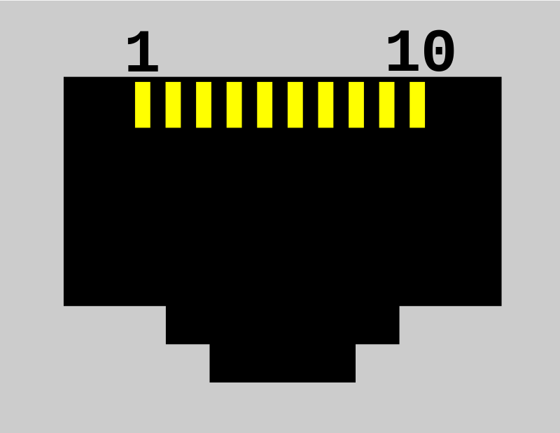
The pin arrangement for a 10P10C socket.
A 10P10C plug.
The 10P10C connector is commonly referred to as an RJ50 connector, although this was never a standard registered jack in the Universal Service Order Codes. The 10P10C has 10 contact positions and 10 contacts.
The most common uses of the 10P10C connector are in proprietary data transfer systems, such as the Digiboard and Equinox Super-Serial multi-port TIA-232 adapters. 10P10C connectors are also used to implement RS-485 interfaces, and for data link connections in APC and Eaton uninterruptible power supplies. In the latter case, a keyed 10P10C plug with a protrusion on the pin 1 side near the back is used.
This connector is also used by some vendors, for example, Cyclades (later absorbed by Equinox) used pin 1 as an "RI" (ring indicator) signal, which is seldom used, allowing an 8P8C plug to be inserted to their 10P10C socket for most applications. The Cisco Systems STS-10X terminal server features this connector. FordNet, a five-pair communications networking medium, also used the 10P10C between terminals.
Motorola uses the 10-pin connector as a microphone connector in several of their mobile radio product lines.
Polycom utilizes this connector on their Conference Link bus to connect their HDX and Group Series codecs and microphones to their SoundStructure audio mixers, although pins 1 and 10 are not used.
The 10-pin connector is also used by Demag Cranes AG in some pendant connections. National Instruments is also using the 10p10c connector for their NI 9237.
MTS Systems Corporation is using the 10p10c connector for their MTS FlexTest® Controller Family.
Source: wikipedia.org