
A counter circuit is usually constructed of a number of flip-flops connected in cascade. Counters are a very widely used component in digital circuits, and are manufactured as separate integrated circuits and also incorporated as parts of larger integrated circuits.
Electronic counters
In electronics, counters can be implemented quite easily using register-type circuits such as the flip-flop, and a wide variety of classified into:
- Asynchronous (ripple) counter – changing state bits are used as clocks to subsequent state flip-flops
- Synchronous counter – all state bits change under control of a single clock
- Decade counter – counts through ten states per stage
- Up/down counter – counts both up and down, under command of a control input
- Ring counter – formed by a shift register with feedback connection in a ring
- Johnson counter – a twisted ring counter
- Cascaded counter
- Modulus counter.
Each is useful for different applications. Usually, counter circuits are digital in nature, and count in natural binary. Many types of counter circuits are available as digital building blocks, for example a number of chips in the 4500 series implement different counters.
Occasionally there are advantages to using a counting sequence other than the natural binary sequence—such as the binary coded decimal counter, a linear-feedback shift register counter, or a Gray-code counter.
Counters are useful for digital clocks and timers, and in oven timers, VCR clocks, etc.
Asynchronous (ripple) counter

Asynchronous counter created from two JK flip-flops
An asynchronous (ripple) counter is a single d-type flip-flop, with its J (data) input fed from its own inverted output. This circuit can store one bit, and hence can count from zero to one before it overflows (starts over from 0). This counter will increment once for every clock cycle and takes two clock cycles to overflow, so every cycle it will alternate between a transition from 0 to 1 and a transition from 1 to 0. Notice that this creates a new clock with a 50% duty cycle at exactly half the frequency of the input clock. If this output is then used as the clock signal for a similarly arranged D flip-flop (remembering to invert the output to the input), one will get another 1 bit counter that counts half as fast. Putting them together yields a two-bit counter:
.PNG)
You can continue to add additional flip-flops, always inverting the output to its own input, and using the output from the previous flip-flop as the clock signal. The result is called a ripple counter, which can count to 2n - 1 where n is the number of bits (flip-flop stages) in the counter. Ripple counters suffer from unstable outputs as the overflows "ripple" from stage to stage, but they do find frequent application as dividers for clock signals, where the instantaneous count is unimportant, but the division ratio overall is (to clarify this, a 1-bit counter is exactly equivalent to a divide by two circuit; the output frequency is exactly half that of the input when fed with a regular train of clock pulses).
The use of flip-flop outputs as clocks leads to timing skew between the count data bits, making this ripple technique incompatible with normal synchronous circuit design styles.
Synchronous counter
![]()
A 4-bit synchronous counter using JK flip-flops
In synchronous counters, the clock inputs of all the flip-flops are connected together and are triggered by the input pulses. Thus, all the flip-flops change state simultaneously (in parallel). The circuit below is a 4-bit synchronous counter. The J and K inputs of FF0 are connected to HIGH. FF1 has its J and K inputs connected to the output of FF0, and the J and K inputs of FF2 are connected to the output of an AND gate that is fed by the outputs of FF0 and FF1. A simple way of implementing the logic for each bit of an ascending counter (which is what is depicted in the adjacent image) is for each bit to toggle when all of the less significant bits are at a logic high state. For example, bit 1 toggles when bit 0 is logic high; bit 2 toggles when both bit 1 and bit 0 are logic high; bit 3 toggles when bit 2, bit 1 and bit 0 are all high; and so on.
Synchronous counters can also be implemented with hardware finite-state machines, which are more complex but allow for smoother, more stable transitions.
Decade counter
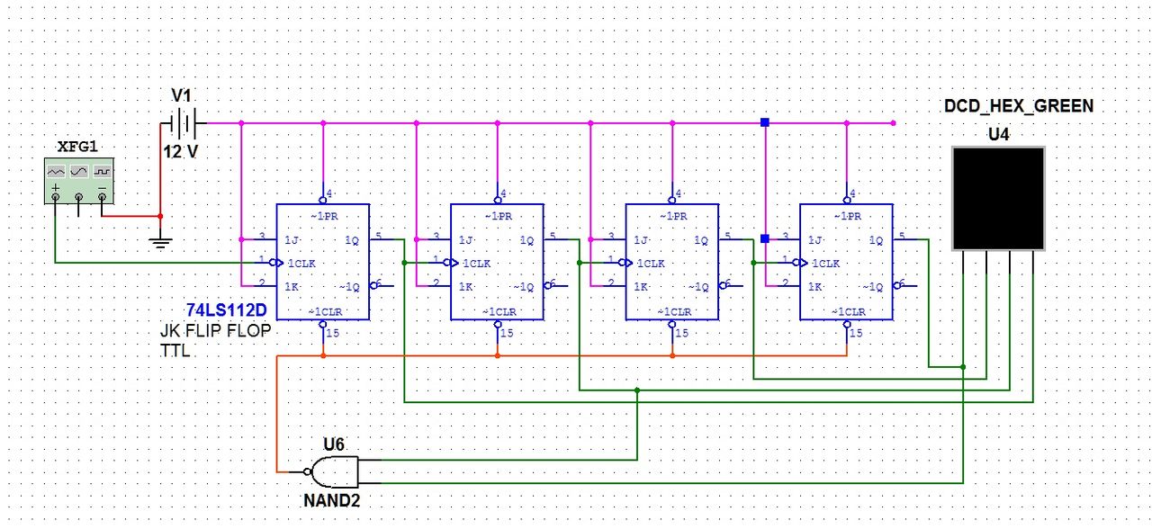
A circuit decade counter using JK Flip-flops (74LS112D) - erratum: Vcc=5V, not 12V on drawing
A decade counter is one that counts in decimal digits, rather than binary. A decade counter may have each (that is, it may count in binary-coded decimal, as the 7490 integrated circuit did) or other binary encodings. "A decade counter is a binary counter that is designed to count to 1010 (decimal 10). An ordinary four-stage counter can be easily modified to a decade counter by adding a NAND gate as in the schematic to the right. Notice that FF2 and FF4 provide the inputs to the NAND gate. The NAND gate outputs are connected to the CLR input of each of the FFs." A decade counter is one that counts in decimal digits, rather than binary. It counts from 0 to 9 and then resets to zero. The counter output can be set to zero by pulsing the reset line low. The count then increments on each clock pulse until it reaches 1001 (decimal 9). When it increments to 1010 (decimal 10) both inputs of the NAND gate go high. The result is that the NAND output goes low, and resets the counter to zero. D going low can be a CARRY OUT signal, indicating that there has been a count of ten.
Ring counter
A ring counter is a circular shift register which is initiated such that only one of its flip-flops is the state one while others are in their zero states.
A ring counter is a shift register (a cascade connection of flip-flops) with the output of the last one connected to the input of the first, that is, in a ring. Typically, a pattern consisting of a single bit is circulated so the state repeats every n clock cycles if n flip-flops are used.
Johnson counter
A Johnson counter (or switch-tail ring counter, twisted ring counter, walking ring counter, or Möbius counter) is a modified ring counter, where the output from the last stage is inverted and fed back as input to the first stage. The register cycles through a sequence of bit-patterns, whose length is equal to twice the length of the shift register, continuing indefinitely. These counters find specialist applications, including those similar to the decade counter, digital-to-analog conversion, etc. They can be implemented easily using D- or JK-type flip-flops.
Computer science counters
In computability theory, a counter is considered a type of memory. A counter stores a single natural number (initially zero) and can be arbitrarily long. A counter is usually considered in conjunction with a finite-state machine (FSM), which can perform the following operations on the counter:
- Check whether the counter is zero
- Increment the counter by one.
- Decrement the counter by one (if it's already zero, this leaves it unchanged).
The following machines are listed in order of power, with each one being strictly more powerful than the one below it:
- Deterministic or non-deterministic FSM plus two counters
- Non-deterministic FSM plus one stack
- Non-deterministic FSM plus one counter
- Deterministic FSM plus one counter
- Deterministic or non-deterministic FSM.
For the first and last, it doesn't matter whether the FSM is a deterministic finite automaton or a nondeterministic finite automaton. They have the same power. The first two and the last one are levels of the Chomsky hierarchy.
The first machine, an FSM plus two counters, is equivalent in power to a Turing machine.
Web counter
A web counter or hit counter is a computer software program that indicates the number of visitors, or hits, a particular webpage has received. Once set up, these counters will be incremented by one every time the web page is accessed in a web browser.
The number is usually displayed as an inline digital image or in plain text or on a physical counter such as a mechanical counter. Images may be presented in a variety of fonts, or styles; the classic example is the wheels of an odometer.
Web counter was popular in the mid to late 1990s and early 2000s, later replaced by more detailed and complete web traffic measures.
Computer based counters
Many automation systems use PC and laptops to monitor different parameters of machines and production data. Counters may count parameters such as the number of pieces produced, the production batch number, and measurements of the amounts of material used.
Mechanical counters
.jpg)
Mechanical counter wheels showing both sides. The bump on the wheel shown at the top engages the ratchet on the wheel below every turn.
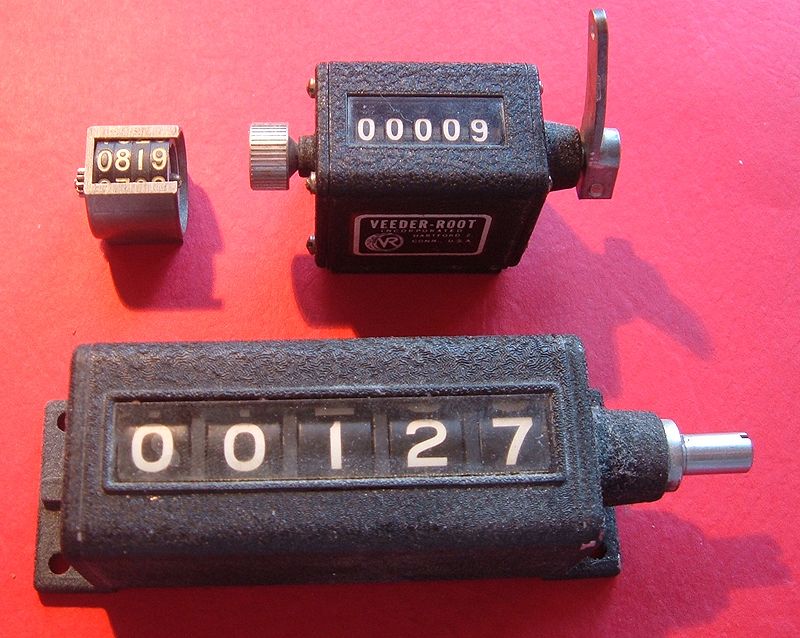
Several mechanical counters
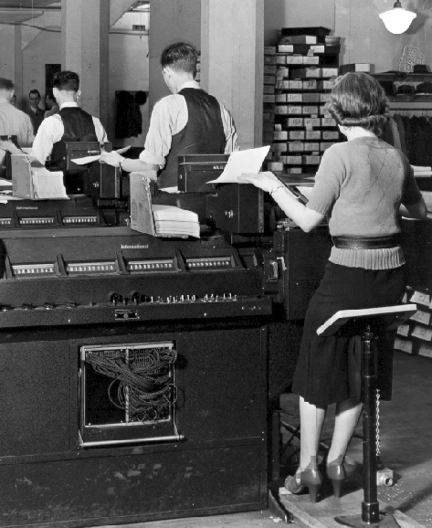
Early IBM tabulating machine using mechanical counters
Long before electronics became common, mechanical devices were used to count events. These are known as tally counters. They typically consist of a series of disks mounted on an axle, with the digits 0 through 9 marked on their edge. The right most disk moves one increment with each event. Each disk except the left-most has a protrusion that, after the completion of one revolution, moves the next disk to the left one increment. Such counters were used as odometers for bicycles and cars and in tape recorders, fuel dispensers, in production machinery as well as in other machinery. One of the largest manufacturers was the Veeder-Root company, and their name was often used for this type of counter.
Hand held tally counters are used mainly for stocktaking and for counting people attending events.
Electromechanical counters were used to accumulate totals in tabulating machines that pioneered the data processing industry.
Source: wikipedia.org