
A screw and a bolt (see Differentiation between bolt and screw below) are similar types of fastener typically made of metal, and characterized by a helical ridge, known as a male thread (external thread). Screws and bolts are used to fasten materials by the engagement of the screw thread with a similar female thread (internal thread) in the matching part.
Screws are often self-threading (also known as self-tapping) where the thread cuts into the material when the screw is turned, creating an internal thread that helps pull fastened materials together and prevent pull-out. There are many screws for a variety of materials; those commonly fastened by screws include wood, sheet metal, and plastic.
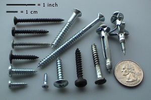
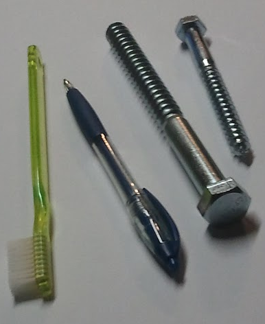
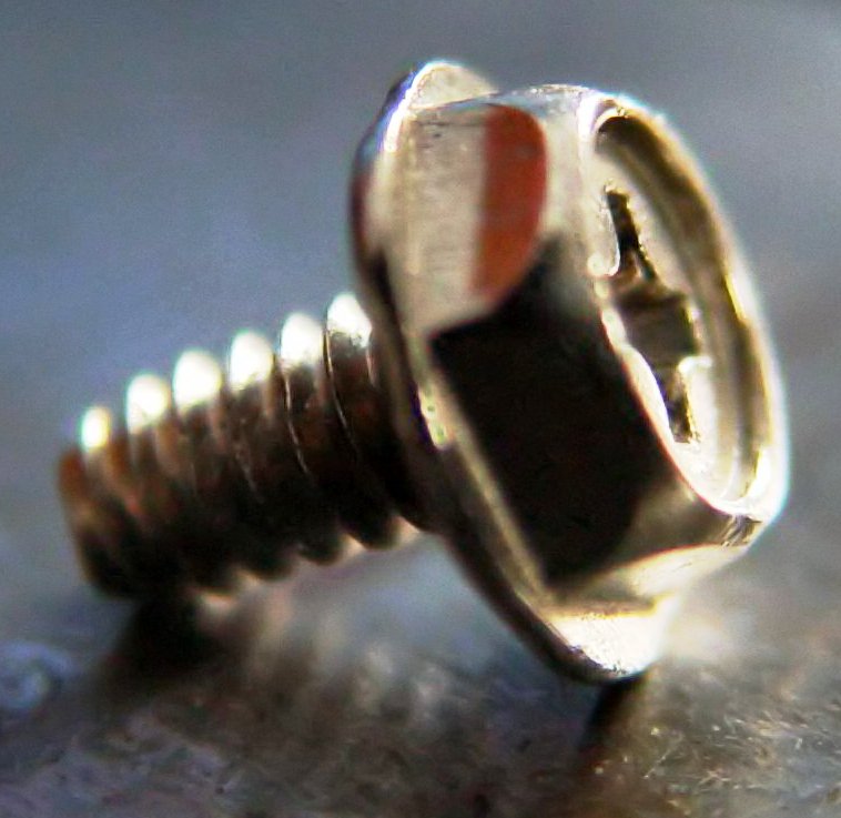
An assortment of screws
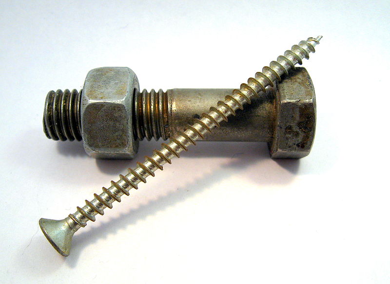
A bolt (with a nut) and a screw
Explanation
A screw is a combination of simple machines—it is, in essence, an inclined plane wrapped around a central shaft, but the inclined plane (thread) also comes to a sharp edge around the outside, which acts a wedge as it pushes into the fastened material, and the shaft and helix also form a wedge in the form of the point. Some screw threads are designed to mate with a complementary thread, known as a female thread (internal thread), often in the form of a nut, or object that has the internal thread formed into it. Other screw threads are designed to cut a helical groove in a softer material as the screw is inserted. The most common uses of screws are to hold objects together and to position objects.

A wood screw: a) head; b) non-threaded shank; c) threaded shank; d) tip.
A screw will usually have a head on one end that allows it to be turned with a tool. Common tools for driving screws include screwdrivers and wrenches. The head is usually larger than the body of the screw, which keeps the screw from being driven deeper than the length of the screw and to provide a bearing surface. There are exceptions. Carriage bolts have a domed head that is not designed to be driven. Set screws often have a head smaller than the outer diameter of the screw. Headless set screws are also called grub screws. J-bolts have a J-shaped head that is not designed to be driven but rather is usually sunk into concrete allowing it to be used as an anchor bolt. The cylindrical portion of the screw from the underside of the head to the tip is known as the shank; it may be fully threaded or partially threaded. The distance between each thread is called the "pitch".
The majority of screws are tightened by clockwise rotation, which is termed a right-hand thread; a common mnemonic device for remembering this when working with screws or bolts is "righty-tighty, lefty-loosey". If the fingers of the right hand are curled around a right-hand thread, it will move in the direction of the thumb when turned in the same direction as the fingers are curled. Screws with left-hand threads are used in exceptional cases, where loads would tend to loosen a right-handed fastener, or when non-interchangeability with right-hand fasteners is required. For example, when the screw will be subject to counterclockwise torque (which would work to undo a right-hand thread), a left-hand-threaded screw would be an appropriate choice. The left side pedal of a bicycle has a left-hand thread.
More generally, a screw may mean any helical device, such as a clamp, a micrometer, a ship's propeller, or an Archimedes' screw water pump.
Differentiation between bolt and screw
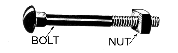
A carriage bolt with a square nut
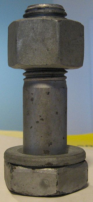
A structural bolt with a hex nut and washer
There is no universally accepted distinction between a screw and a bolt. A simple distinction that is often true, although not always, is that a bolt passes through a substrate and takes a nut on the other side, whereas a screw takes no nut because it threads directly into the substrate (a screw screws into something, a bolt bolts several things together). So, as a general rule, when buying a packet of "screws", nuts would not be expected to be included, but bolts are often sold with matching nuts. Part of the confusion over this is likely due to regional or dialectical differences. Machinery's Handbook describes the distinction as follows:
A bolt is an externally threaded fastener designed for insertion through holes in assembled parts, and is normally intended to be tightened or released by torquing a nut. A screw is an externally threaded fastener capable of being inserted into holes in assembled parts, of mating with a preformed internal thread or forming its own thread, and of being tightened or released by torquing the head. An externally threaded fastener which is prevented from being turned during assembly and which can be tightened or released only by torquing a nut is a bolt. (Example: round head bolts, track bolts, plow bolts.) An externally threaded fastener that has thread form which prohibits assembly with a nut having a straight thread of multiple pitch length is a screw. (Example: wood screws, tapping screws.)
This distinction is consistent with ASME B18.2.1 and some dictionary definitions for screw and bolt.
The issue of what is a screw and what is a bolt is not completely resolved with Machinery's Handbook distinction, however, because of confounding terms, the ambiguous nature of some parts of the distinction, and usage variations. Some of these issues are discussed below:
Wood screws
Early wood screws were made by hand, with a series of files, chisels, and other cutting tools, and these can be spotted easily by noting the irregular spacing and shape of the threads, as well as file marks remaining on the head of the screw and in the area between threads. Many of these screws had a blunt end, completely lacking the sharp tapered point on nearly all modern wood screws. Eventually, lathes were used to manufacture wood screws, with the earliest patent being recorded in 1760 in England. During the 1850s swaging tools were developed to provide a more uniform and consistent thread. Screws made with these tools have rounded valleys with sharp and rough threads. Some wood screws were made with cutting dies as early as the late 1700s (possibly even before 1678 when the book content was first published in parts).
Once screw turning machines were in common use, most commercially available wood screws were produced with this method. These cut wood screws are almost invariably tapered, and even when the tapered shank is not obvious, they can be discerned because the threads do not extend past the diameter of the shank. Such screws are best installed after drilling a pilot hole with a tapered drill bit. The majority of modern wood screws, except for those made of brass, are formed on thread rolling machines. These screws have a constant diameter, threads with a larger diameter than the shank, and are stronger because the rolling process does not cut the grain of the metal.
Machine screws
ASME standards specify a variety of "Machine Screws" in diameters ranging up to 0.75 in (19.05 mm). These fasteners are often used as bolts with nuts, but also often driven into tapped holes (without nuts). They might be considered a screw or a bolt based on the Machinery's Handbook distinction. In practice, they tend to be mostly available in smaller sizes and the smaller sizes are referred to as screws or less ambiguously as machine screws, although some kinds of machine screw can be referred to as stove bolts.
Hex cap screws
ASME standard B18.2.1-1996 specifies Hex Cap Screws whose size range is 0.25–3 in (6.35–76.20 mm) in diameter. These fasteners are very similar to hex bolts. They differ mostly in that they are manufactured to tighter tolerances than the corresponding bolts. Machinery's Handbook refers parenthetically to these fasteners as "Finished Hex Bolts". Reasonably, these fasteners might be referred to as bolts, but based on the US government document Distinguishing Bolts from Screws, the US government might classify them as screws because of the tighter tolerance. In 1991 responding to an influx of counterfeit fasteners Congress passed PL 101-592 "Fastener Quality Act" This resulted in the rewriting of specifications by the ASME B18 committee. B18.2.1 was re-written and as a result they eliminated the "Finished Hex Bolts" and renamed them the "Hex Cap Screw"—a term that had existed in common usage long before, but was now also being codified as an official name for the ASME B18 standard.
Lug bolts and head bolts
These terms refer to fasteners that are designed to be threaded into a tapped hole that is in part of the assembly and so based on the Machinery's Handbook distinction they would be screws. Here common terms are at variance with Machinery's Handbook distinction.
Lag screw
Lag screws, also called lag bolts
Lag screws (US) or coach screws (UK, Australia, and New Zealand) (also referred to as lag bolts or coach bolts, although this is a misnomer) are large wood screws. The head is typically an external hex. Metric hex-headed lag screws are covered by DIN 571. Inch square-headed and hex-headed lag screws are covered by ASME B18.2.1. A typical lag screw can range in diameter from 4 to 20 mm or #10 to 1.25 in (4.83 to 31.75 mm), and lengths from 16 to 200 mm or 1⁄4 to 6 in (6.35 to 152.40 mm) or longer, with the coarse threads of a wood-screw or sheet-metal-screw threadform (but larger).
The materials are usually carbon steel substrate with a coating of zinc galvanization (for corrosion resistance). The zinc coating may be bright (electroplated), yellow (electroplated), or dull gray hot-dip galvanized. Lag screws are used to lag together lumber framing, to lag machinery feet to wood floors, and for other heavy carpentry applications. The attributive modifier lag came from an early principal use of such fasteners: the fastening of lags such as barrel staves and other similar parts.
These fasteners are "screws" according to the Machinery's Handbook criteria, and the obsolescent term "lag bolt" has been replaced by "lag screw" in the Handbook. However, to many tradesmen, they are "bolts", because they are large, with hex or square heads.
United States government standards
The federal government of the United States made an effort to formalize the difference between a bolt and a screw, because different tariffs apply to each. The document seems to have no significant effect on common usage and does not eliminate the ambiguous nature of the distinction between screws and bolts for some threaded fasteners. The document also reflects (although it probably did not originate) significant confusion of terminology usage that differs between the legal/statutory/regulatory community and the fastener industry. The legal/statutory/regulatory wording uses the terms "coarse" and "fine" to refer to the tightness of the tolerance range, referring basically to "high-quality" or "low-quality", but this is a poor choice of terms, because those terms in the fastener industry have a different meaning (referring to the steepness of the helix's lead).
Historical issue
Old USS and SAE standards defined cap screws as fasteners with shanks that were threaded to the head and bolts as fasteners with shanks that were partially unthreaded. The relationship of this rule to the idea that a bolt by definition takes a nut is clear (because the unthreaded section of the shank, which is called the grip, was expected to pass through the substrate without threading into it). This is now an obsolete distinction, although large bolts still often have unthreaded sections of shank.
Although there is no reason to consider this definition obsolete, because it is far from clear that "a bolt by definition takes a nut". Using a coach "bolt" as an example (and it has been a 'bolt' for a very long time). It was not originally intended to receive a nut, but did have a shank. Its purpose was not to pass through the entire substrate but only one piece of it, while the threaded portion bit into the other in order to draw, and clamp the materials together. The 'carriage' bolt was derived from this and was employed more to speed up manufacturing than achieve a different function. The carriage bolt passes through both pieces of materials and employs a nut to provide the clamping force. Both are still, however, bolts.
Controlled vocabulary versus natural language
The distinctions above are enforced in the controlled vocabulary of standards organizations. Nevertheless, there are sometimes differences between the controlled vocabulary and the natural language use of the words by machinists, auto mechanics and others. These differences reflect linguistic evolution shaped by the changing of technology over centuries. The words bolt and screw have both existed since before today's modern mix of fastener types existed, and the natural usage of those words has evolved retronymously in response to the technological change. (That is, the use of words as names for objects changes as the objects change.) Non-threaded fasteners predominated until the advent of practical, inexpensive screw-cutting in the early 19th century. The basic meaning of the word screw has long involved the idea of a helical screw thread, but the Archimedes screw and the screw gimlet (like a corkscrew) preceded the fastener.
The word bolt is also a very old word, and it was used for centuries to refer to metal rods that passed through the substrate to be fastened on the other side, often via nonthreaded means (clinching, forge welding, pinning, wedging, etc.). The connection of this sense to the sense of a door bolt or the crossbow bolt is apparent. In the 19th century, bolts fastened via screw threads were often called screw bolts in contradistinction to clench bolts.
In common usage, the distinction (not rigorous) is often that screws are smaller than bolts, and that screws are generally tapered while bolts are not. For example, cylinder head bolts are called "bolts" (at least in North American usage) despite the fact that by some definitions they ought to be called "screws". Their size and their similarity to a bolt that would take a nut seem linguistically to overrule any other factors in this natural word choice proclivity.
Other distinctions
Bolts have been defined as headed fasteners having external threads that meet an exacting, uniform bolt thread specification (such as ISO metric screw thread M, MJ, Unified Thread Standard UN, UNR, and UNJ) such that they can accept a non-tapered nut. Screws are then defined as headed, externally threaded fasteners that do not meet the above definition of bolts. These definitions of screw and bolt eliminate the ambiguity of the Machinery's handbook distinction. And it is for that reason, perhaps, that some people favor them. However, they are neither compliant with common usage of the two words nor are they compliant with formal specifications.
A possible distinction is that a screw is designed to cut its own thread; it has no need for access from or exposure to the opposite side of the component being fastened to. This definition of screw is further reinforced by the consideration of the developments of fasteners such as Tek Screws, with either round or hex heads, for roof cladding, self-drilling and self-tapping screws for various metal fastening applications, roof batten screws to reinforce the connection between the roof batten and the rafter, decking screws etc. On the other hand, a bolt is the male part of a fastener system designed to be accepted by a pre-equipped socket (or nut) of exactly the same thread design.
Types of screws and bolts
Threaded fasteners either have a tapered shank or a non-tapered shank. Fasteners with tapered shanks are designed to either be driven into a substrate directly or into a pilot hole in a substrate. Mating threads are formed in the substrate as these fasteners are driven in. Fasteners with a non-tapered shank are designed to mate with a nut or to be driven into a tapped hole.
- Fasteners with a tapered shank
- Fasteners with a non-tapered shank
- Fasteners with built in washers
A fastener with a built in washer is called a SEM or SEMS, short for pre-asSEMbled. It could be fitted on either a tapered or non-tapered shank.
Other threaded fasteners
Superbolt, or multi-jackbolt tensioner
A superbolt, or multi-jackbolt tensioner is an alternative type of fastener that retrofits or replaces existing nuts, bolts, or studs. Tension in the bolt is developed by torquing individual jackbolts, which are threaded through the body of the nut and push against a hardened washer. Because of this, the amount of torque required to achieve a given preload is reduced. Installation and removal of any size tensioner is achieved with hand tools, which can be advantageous when dealing with large diameter bolting applications.
Bone screws
The field of screws and other hardware for internal fixation within the body is huge and diverse. Like prosthetics, it integrates the industrial and medicosurgical fields, causing manufacturing technologies (such as machining, CAD/CAM, and 3D printing) to intersect with the art and science of medicine. Like aerospace and nuclear power, this field involves some of the highest technology for fasteners, as well as some of the highest prices, for the simple reason that performance, longevity, and quality have to be excellent in such applications. Bone screws tend to be made of stainless steel or titanium, and they often have high-end features such as conical threads, multistart threads, cannulation (hollow core), and proprietary screw drive types (some not seen outside of these applications).
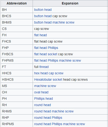
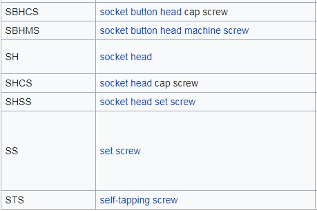
List of abbreviations for types of screws
These abbreviations have jargon currency among fastener specialists (who, working with many screw types all day long, have need to abbreviate repetitive mentions). The smaller basic ones can be built up into the longer ones; for example, if you know that "FH" means "flat head", then you may be able to parse the rest of a longer abbreviation containing "FH".
These abbreviations are not universally standardized across corporations; each corporation can coin their own. The more obscure ones may not be listed here.
The extra spacing between linked terms below helps the reader to see the correct parsing at a glance.
Materials
Screws and bolts are usually made of steel. Where great resistance to weather or corrosion is required, like in very small screws or medical implants, materials such as stainless steel, brass, titanium, bronze, silicon bronze or monel may be used.
Galvanic corrosion of dissimilar metals can be prevented (using aluminum screws for double-glazing tracks for example) by a careful choice of material. Some types of plastic, such as nylon or polytetrafluoroethylene (PTFE), can be threaded and used for fastenings requiring moderate strength and great resistance to corrosion or for the purpose of electrical insulation.
Often a surface coating is used to protect the fastener from corrosion (e.g. bright zinc plating for steel screws), to impart a decorative finish (e.g. japanning) or otherwise alter the surface properties of the base material.
Selection criteria of the screw materials include: size, required strength, resistance to corrosion, joint material, cost and temperature.
Bolted joints
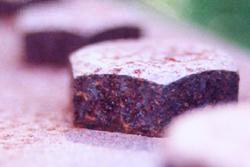
Rusty hexagonal bolt heads
The American Institute of Steel Construction (AISC) 13th Edition Steel Design Manual section 16.1 chapter J-3 specifies the requirements for bolted structural connections. Structural bolts replaced rivets due to the decreasing cost and increasing strength of structural bolts in the 20th century. Connections are formed with two types of joints: slip-critical connections and bearing connections. In slip-critical connections, movement of the connected parts is a serviceability condition and bolts are tightened to a minimum required pretension. Slip is prevented through friction of the "faying" surface, that is the plane of shear for the bolt and where two members make contact. Because friction is proportional to the normal force, connections must be sized with bolts numerous and large enough to provide the required load capacity. However, this greatly decreases the shear capacity of each bolt in the connection. The second (and more common type) of connection is a bearing connection. In this type of connection, the bolts carry the load through shear and are only tightened to a "snug-fit". These connections require fewer bolts than slip-critical connections and therefore are a less expensive alternative. Slip-critical connections are more common on flange plates for beam and column splices and moment critical connections. Bearing type connections are used in lightweight structures and in member connections where slip is not important and prevention of structural failure is the design constraint. Common bearing type connections include: shear tabs, beam supports, gusset plates in trusses.
Mechanical classifications
The numbers stamped on the head of the bolt are referred to the grade of the bolt used in certain application with the strength of a bolt. High-strength steel bolts usually have a hexagonal head with an ISO strength rating (called property class) stamped on the head. And the absence of marking/number indicates a lower grade bolt with low strength. The property classes most often used are 5.8, 8.8, and 10.9. The number before the point is the ultimate tensile strength in MPa divided by 100. The number after the point is the multiplier ratio of yield strength to ultimate tensile strength. For example, a property class 5.8 bolt has a nominal (minimum) ultimate tensile strength of 500 MPa, and a tensile yield strength of 0.8 times ultimate tensile strength or 0.8 (500) = 400 MPa.
Ultimate tensile strength is the tensile stress at which the bolt fails. Tensile yield strength is the stress at which the bolt will yield in tension across the entire section of the bolt and receive a permanent set (an elongation from which it will not recover when the force is removed) of 0.2% offset strain. Proof strength is the usable strength of the fastener. Tension testing of a bolt up to the proof load should not cause permanent set of the bolt and should be conducted on actual fasteners rather than calculated. If a bolt is tensioned beyond the proof load, it may behave in plastic manner due to yielding in the threads and the tension preload may be lost due to the permanent plastic deformations. When elongating a fastener prior to reaching the yield point, the fastener is said to be operating in the elastic region; whereas elongation beyond the yield point is referred to as operating in the plastic region of the bolt material. If a bolt is loaded in tension beyond its proof strength, the yielding at the net root section of the bolt will continue until the entire section is begins to yield and it has exceeded its yield strength. If tension increases, the bolt fractures at its ultimate strength.
Mild steel bolts have property class 4.6, which is 400 MPa ultimate strength and 0.6*400=240 MPa yield strength. High-strength steel bolts have property class 8.8, which is 800 MPa ultimate strength and 0.8*800=640 MPa yield strength or above.
The same type of screw or bolt can be made in many different grades of material. For critical high-tensile-strength applications, low-grade bolts may fail, resulting in damage or injury. On SAE-standard bolts, a distinctive pattern of marking is impressed on the heads to allow inspection and validation of the strength of the bolt. However, low-cost counterfeit fasteners may be found with actual strength far less than indicated by the markings. Such inferior fasteners are a danger to life and property when used in aircraft, automobiles, heavy trucks, and similar critical applications.
Metric
The international standards for metric externally threaded fasteners are ISO 898-1 for property classes produced from carbon steels and ISO 3506-1 for property classes produced from corrosion resistant steels.
Inch
There are many standards governing the material and mechanical properties of imperial sized externally threaded fasteners. Some of the most common consensus standards for grades produced from carbon steels are ASTM A193, ASTM A307, ASTM A354, ASTM F3125, and SAE J429. Some of the most common consensus standards for grades produced from corrosion resistant steels are ASTM F593 & ASTM A193.
Screw head shapes

(a) pan, (b) dome (button), (c) round, (d) truss (mushroom), (e) flat (countersunk), (f) oval (raised head)
Combination flanged-hex/Phillips-head screw used in computers
Pan head
A low disc with a rounded, high outer edge with large surface area
Button or dome head
Cylindrical with a rounded top
Round head
A dome-shaped head used for decoration.
Mushroom or Truss head
Lower-profile dome designed to prevent tampering
Countersunk or flat head
Conical, with flat outer face and tapering inner face allowing it to sink into the material. The angle of the screw is measured as the full angle of the cone.
Oval or raised head
A decorative screw head with a countersunk bottom and rounded top. Also known as "raised countersunk" (UK)
Bugle head
Similar to countersunk, but there is a smooth progression from the shank to the angle of the head, similar to the bell of a bugle
Cheese head
Disc with cylindrical outer edge, height approximately half the head diameter
Fillister head
Cylindrical, but with a slightly convex top surface. Height to diameter ratio is larger than cheese head.
Flanged head
A flanged head can be any of the above head styles (except the countersunk styles) with the addition of an integrated flange at the base of the head. This eliminates the need for a flat washer.
Some varieties of screw are manufactured with a break-away head, which snaps off when adequate torque is applied. This prevents tampering and also provides an easily inspectable joint to guarantee proper assembly. An example of this is the shear bolts used on vehicle steering columns, to secure the ignition switch.
Types of screw drives
Modern screws employ a wide variety of drive designs, each requiring a different kind of tool to drive in or extract them. The most common screw drives are the slotted and Phillips in the US; hex, Robertson, and Torx are also common in some applications, and Pozidriv has almost completely replaced Phillips in Europe. Some types of drive are intended for automatic assembly in mass-production of such items as automobiles. More exotic screw drive types may be used in situations where tampering is undesirable, such as in electronic appliances that should not be serviced by the home repair person.
Tools
The hand tool used to drive in most screws is called a screwdriver. A power tool that does the same job is a power screwdriver; power drills may also be used with screw-driving attachments. Where the holding power of the screwed joint is critical, torque-measuring and torque-limiting screwdrivers are used to ensure sufficient but not excessive force is developed by the screw. The hand tool for driving hex head threaded fasteners is a spanner (UK usage) or wrench (US usage), while a nut setter is used with a power screw driver.
ISO metric screw thread
The basic principles of the ISO metric screw thread are defined in international standard ISO 68-1 and preferred combinations of diameter and pitch are listed in ISO 261. The smaller subset of diameter and pitch combinations commonly used in screws, nuts and bolts is given in ISO 262. The most commonly used pitch value for each diameter is the coarse pitch. For some diameters, one or two additional fine pitch variants are also specified, for special applications such as threads in thin-walled pipes. ISO metric screw threads are designated by the letter M followed by the major diameter of the thread in millimetres (e.g. M8). If the thread does not use the normal coarse pitch (e.g. 1.25 mm in the case of M8), then the pitch in millimeters is also appended with a multiplication sign (e.g. "M8×1" if the screw thread has an outer diameter of 8 mm and advances by 1 mm per 360° rotation).
The nominal diameter of a metric screw is the outer diameter of the thread. The tapped hole (or nut) into which the screw fits, has an internal diameter which is the size of the screw minus the pitch of the thread. Thus, an M6 screw, which has a pitch of 1 mm, is made by threading a 6 mm shank, and the nut or threaded hole is made by tapping threads into a hole of 5 mm diameter (6 mm - 1 mm).
Metric hexagon bolts, screws and nuts are specified, for example, in International Standards ISO 4014, ISO 4017, and ISO 4032. The following table lists the relationship given in these standards between the thread size and the maximum width across the hexagonal flats (wrench size).
Whitworth
The first person to create a standard (in about 1841) was the English engineer Sir Joseph Whitworth. Whitworth screw sizes are still used, both for repairing old machinery and where a coarser thread than the metric fastener thread is required. Whitworth became British Standard Whitworth, abbreviated to BSW (BS 84:1956) and the British Standard Fine (BSF) thread was introduced in 1908 because the Whitworth thread was too coarse for some applications. The thread angle was 55°, and the depth and pitch varied with the diameter of the thread (i.e., the bigger the bolt, the coarser the thread). Spanners for Whitworth bolts are marked with the size of the bolt, not the distance across the flats of the screw head.
The most common use of a Whitworth pitch nowadays is in all UK scaffolding. Additionally, the standard photographic tripod thread, which for small cameras is 1/4" Whitworth (20 tpi) and for medium/large format cameras is 3/8" Whitworth (16 tpi). It is also used for microphone stands and their appropriate clips, again in both sizes, along with "thread adapters" to allow the smaller size to attach to items requiring the larger thread. Note that while 1/4" UNC bolts fit 1/4" BSW camera tripod bushes, yield strength is reduced by the different thread angles of 60° and 55° respectively.
British Association screw thread
British Association (BA) screw threads, named after the British Association for Advancement of Science, were devised in 1884 and standardised in 1903. Screws were described as "2BA", "4BA" etc., the odd numbers being rarely used, except in equipment made prior to the 1970s for telephone exchanges in the UK. This equipment made extensive use of odd-numbered BA screws, in order—it may be suspected—to reduce theft. BA threads are specified by British Standard BS 93:1951 "Specification for British Association (B.A.) screw threads with tolerances for sizes 0 B.A. to 16 B.A."
While not related to ISO metric screws, the sizes were actually defined in metric terms, a 0BA thread having a 6 mm diameter and 1 mm pitch. Other threads in the BA series are related to 0BA in a geometric series with the common factors 0.9 and 1.2.
BA threads are still common in some niche applications. Certain types of fine machinery, such as moving-coil meters and clocks, tend to have BA threads wherever they are manufactured. BA sizes were also used extensively in aircraft, especially those manufactured in the United Kingdom. BA sizing is still used in railway signalling, mainly for the termination of electrical equipment and cabling.
BA threads are extensively used in Model Engineering where the smaller hex head sizes make scale fastenings easier to represent. As a result, many UK Model Engineering suppliers still carry stocks of BA fasteners up to typically 8BA and 10BA. 5BA is also commonly used as it can be threaded onto 1/8 rod.
Unified Thread Standard
The Unified Thread Standard (UTS) is most commonly used in the United States, but is also extensively used in Canada and occasionally in other countries. The size of a UTS screw is described using the following format: X-Y, where X is the nominal size (the hole or slot size in standard manufacturing practice through which the shank of the screw can easily be pushed) and Y is the threads per inch (TPI). For sizes 1⁄4 inch and larger the size is given as a fraction; for sizes less than this an integer is used, ranging from 0 to 16. The integer sizes can be converted to the actual diameter by using the formula 0.060 + (0.013 × number). For example, a #4 screw is 0.060 + (0.013 × 4) = 0.060 + 0.052 = 0.112 inches in diameter. There are also screw sizes smaller than "0" (zero or ought). The sizes are 00, 000, 0000 which are usually referred to as two ought, three ought, and four ought. Most eyeglasses have the bows screwed to the frame with 00-72 (pronounced double ought – seventy two) size screws. To calculate the major diameter of "ought" size screws count the number of 0's and multiply this number by 0.013 and subtract from 0.060. For example, the major diameter of a 000-72 screw thread is .060 – (3 x .013) = 0.060 - 0.039 = .021 inches. For most size screws there are multiple TPI available, with the most common being designated a Unified Coarse Thread (UNC or UN) and Unified Fine Thread (UNF or UF). Note: In countries other than the United States and Canada, the ISO Metric Screw Thread System is primarily used today. Unlike most other countries the United States and Canada still use the Unified (Inch) Thread System. However, both are moving over to the ISO Metric System. It is estimated that approximately 60% of screw threads in use in the United States are still inch based.
Manufacture
There are three steps in manufacturing a screw: heading, thread rolling, and coating. Screws are normally made from wire, which is supplied in large coils, or round bar stock for larger screws. The wire or rod is then cut to the proper length for the type of screw being made; this workpiece is known as a blank. It is then cold headed, which is a cold working process. Heading produces the head of the screw. The shape of the die in the machine dictates what features are pressed into the screw head; for example a flat head screw uses a flat die. For more complicated shapes two heading processes are required to get all of the features into the screw head. This production method is used because heading has a very high production rate, and produces virtually no waste material. Slotted head screws require an extra step to cut the slot in the head; this is done on a slotting machine. These machines are essentially stripped down milling machines designed to process as many blanks as possible.
The blanks are then polished again prior to threading. The threads are usually produced via thread rolling; however, some are cut. The workpiece is then tumble finished with wood and leather media to do final cleaning and polishing. For most screws, a coating, such as electroplating with zinc (galvanizing) or applying black oxide, is applied to prevent corrosion.
History
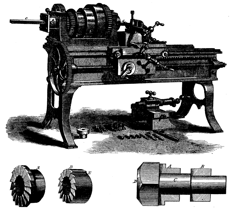
A lathe of 1871, equipped with leadscrew and change gears for single-point screw-cutting.
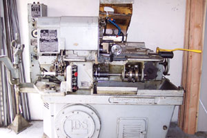
A Brown & Sharpe single-spindle screw machine.
While a recent hypothesis attributes the Archimedes' screw to Sennacherib, King of Assyria, archaeological finds and pictorial evidence only appear in the Hellenistic period and the standard view holds the device to be a Greek invention, most probably by the 3rd century BC polymath Archimedes. Though resembling a screw, this is not a screw in the usual sense of the word.
Earlier, the screw had been described by the Greek mathematician Archytas of Tarentum (428–350 BC). By the 1st century BC, wooden screws were commonly used throughout the Mediterranean world in screw presses for pressing olive oil from olives and pressing juice from grapes in winemaking. Metal screws used as fasteners were rare in Europe before the 15th century, if known at all.
Rybczynski has shown that handheld screwdrivers (formerly called "turnscrews" in English, in more direct parallel to their original French name, tournevis) have existed since medieval times (the 1580s at the latest), although they probably did not become truly widespread until after 1800, once threaded fasteners had become commodified, as detailed below.
There were many forms of fastening in use before threaded fasteners became widespread. They tended to involve carpentry and smithing rather than machining, and they involved concepts such as dowels and pins, wedging, mortises and tenons, dovetails, nailing (with or without clenching the nail ends), forge welding, and many kinds of binding with cord made of leather or fiber, using many kinds of knots. Prior to the mid-19th century, cotter pins or pin bolts, and "clinch bolts" (now called rivets), were used in shipbuilding. Glues also existed, although not in the profusion seen today.
The metal screw did not become a common fastener until machine tools for their mass production were developed toward the end of the 18th century. This development blossomed in the 1760s and 1770s along two separate paths that soon converged: the mass production of wood screws (meaning screws made of metal to be used in wood) in a specialized, single-purpose, high-volume-production machine tool; and the low-count, toolroom-style production of machine screws (V-thread) with easy selection among various pitches (whatever the machinist happened to need on any given day).
The first path was pioneered by brothers Job and William Wyatt of Staffordshire, UK, who patented in 1760 a machine that we might today best call a screw machine of an early and prescient sort. It made use of a leadscrew to guide the cutter to produce the desired pitch, and the slot was cut with a rotary file while the main spindle held still (presaging live tools on lathes 250 years later). Not until 1776 did the Wyatt brothers have a wood-screw factory up and running. Their enterprise failed, but new owners soon made it prosper, and in the 1780s they were producing 16,000 screws a day with only 30 employees—the kind of industrial productivity and output volume that would later be characteristic of modern industry but was revolutionary at the time.
Meanwhile, English instrument maker Jesse Ramsden (1735–1800) was working on the toolmaking and instrument-making end of the screw-cutting problem, and in 1777 he invented the first satisfactory screw-cutting lathe. The British engineer Henry Maudslay (1771–1831) gained fame by popularizing such lathes with his screw-cutting lathes of 1797 and 1800, containing the trifecta of leadscrew, slide rest, and change-gear gear train, all in the right proportions for industrial machining. In a sense he unified the paths of the Wyatts and Ramsden and did for machine screws what had already been done for wood screws, i.e., significant easing of production spurring commodification. His firm would remain a leader in machine tools for decades afterward. A misquoting of James Nasmyth popularized the notion that Maudslay had invented the slide rest, but this was incorrect; however, his lathes helped to popularize it.
These developments of the 1760–1800 era, with the Wyatts and Maudslay being arguably the most important drivers, caused great increase in the use of threaded fasteners. Standardization of threadforms began almost immediately, but it was not quickly completed; it has been an evolving process ever since. Further improvements to the mass production of screws continued to push unit prices lower and lower for decades to come, throughout the 19th century.
In 1821, the first screw factory in the United States was built by Hardman Philips on Moshannon Creek, near Philipsburg for the manufacture of blunt metal screws. An expert in screw manufacture, Thomas Lever was brought over from England to run the factory. The mill was run by steam and water power, and the fuel used was hardwood charcoal. The screws were made from wire prepared by “rolling and wire drawing apparatus” from iron manufactured at a nearby forge. The screw mill was not a commercial success. It eventually failed due to competition from the lower cost, gimlet-pointed screw and ceased operations in 1836.
The American development of the turret lathe (1840s) and of automatic screw machines derived from it (1870s) drastically reduced the unit cost of threaded fasteners by increasingly automating the machine tool control. This cost reduction spurred ever greater use of screws.
Throughout the 19th century, the most commonly used forms of screw head (that is, drive types) were simple internal-wrenching straight slots and external-wrenching squares and hexagons. These were easy to machine and served most applications adequately. Rybczynski describes a flurry of patents for alternative drive types in the 1860s through 1890s, but explains that these were patented but not manufactured due to the difficulties and expense of doing so at the time. In 1908, Canadian P. L. Robertson was the first to make the internal-wrenching square socket drive a practical reality by developing just the right design (slight taper angles and overall proportions) to allow the head to be stamped easily but successfully, with the metal cold forming as desired rather than being sheared or displaced in unwanted ways. Practical manufacture of the internal-wrenching hexagon drive (hex socket) shortly followed in 1911.
In the early 1930s, the Phillips-head screw was popularized by American Henry F. Phillips.
Threadform standardization further improved in the late 1940s, when the ISO metric screw thread and the Unified Thread Standard were defined.
Precision screws, for controlling motion rather than fastening, developed around the turn of the 19th century, were one of the central technical advances, along with flat surfaces, that enabled the industrial revolution. They are key components of micrometers and lathes.
Other fastening methods
Alternative fastening methods are:
- nails
- rivets
- pins (dowel pins, taper pins, roll pins, spring pins, cotter pins)
- pinned shafts (keyed shafts, woodruff keys, gibb-headed key)
- screw bolt, pin bolt or cotter bolt, and clench bolt- as used in clinker boat building
- welding
- soldering
- brazing
- joinery (mortise & tenon, dovetailing, box joints, lap joints)
- gluing
- taping
- clinch fastening
Source: wikipedia.org